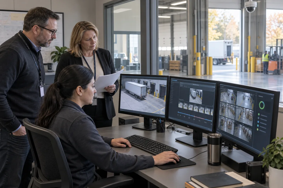
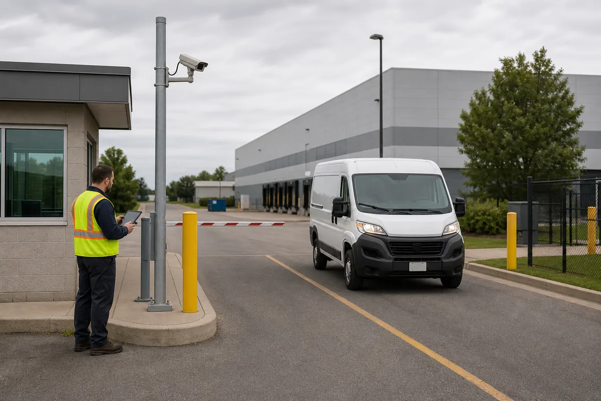
IP Security Camera Network Design: A Practical Enterprise Guide
Design a resilient IP camera network with realistic bandwidth, PoE, segmentation, time, storage, monitoring, and recovery requirements.
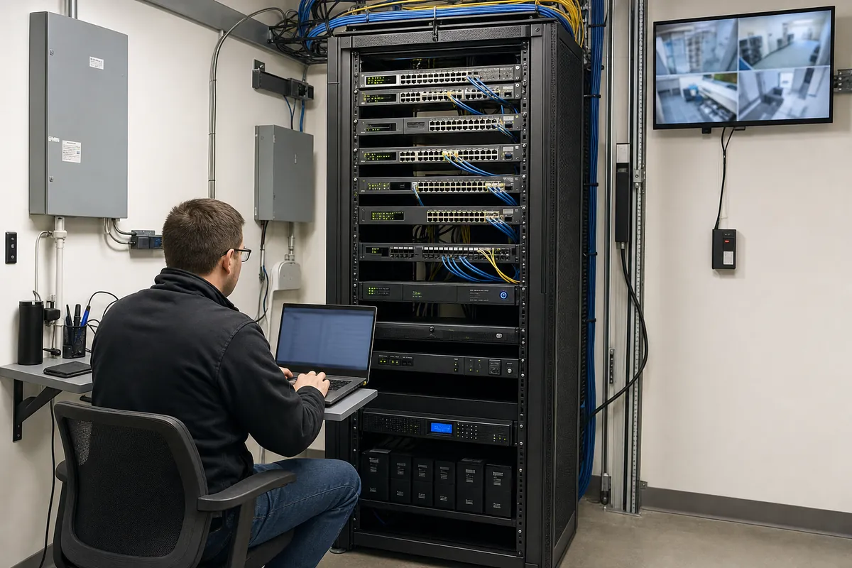
An IP video system can fail while every camera still has power. Congested uplinks, incorrect multicast, exhausted PoE, time drift, storage latency, certificate expiry, and uncontrolled remote access can each undermine the service.
Enterprise design starts by defining the workload and failure behaviour, then builds the network around it.
Model Every Video Flow
Do not calculate only camera-to-recorder traffic. Document:
- primary and secondary recording streams;
- live viewing and video-wall demand;
- mobile or remote viewing;
- analytics metadata and event traffic;
- edge-storage recovery or backfill;
- failover-recorder traffic;
- export and investigation transfers;
- firmware, configuration, certificate, DNS, and time services;
- monitoring and log collection.
For each camera, obtain realistic average and peak bit rates using the intended scene, resolution, frame rate, codec, quality target, keyframe interval, and day/night condition. Leaves, rain, snow, noise, crowds, and busy conveyors create more change than a quiet demonstration wall and can drive higher bit rates.
Separate Access and Uplink Calculations
At the access layer, verify per-port speed, switch backplane capacity, PoE class, and environmental rating. At the distribution layer, add simultaneous streams and failure scenarios.
For example, an uplink that looks comfortable during normal primary recording may become a bottleneck when a recorder fails over, several operators open live views, and edge devices backfill stored video. Model the concurrent case the business expects to survive.
Keep design headroom explicit. Headroom is not a substitute for measurement; it is capacity reserved for bursts, growth, and operational change.
Engineer the PoE Budget
Add the maximum expected draw of every powered device, including heaters, infrared illumination, PTZ motors, intercom audio, and accessories. Compare the total with the switch’s available PoE budget under the selected power-supply and redundancy mode.
Then ask:
- Does a redundant power-supply failure reduce the available PoE budget?
- Which ports are shed first under overload?
- Can the UPS carry the switch at full PoE load?
- Are long cable runs or intermediate extenders documented?
- Can support staff see actual draw and power faults?
Reserve capacity for replacements. A later camera model may draw more power even when it serves the same view.
Build Security Zones, Not Just a VLAN
A VLAN without enforced routing policy is organization, not protection. Use dedicated zones for field devices, recording, management, and operator access where risk warrants it. Permit only necessary flows, initiated in the required direction.
Useful controls include:
- unique device credentials and disabled default accounts;
- administrator access through managed workstations or a controlled jump path;
- no direct inbound internet exposure;
- restricted outbound cloud connectivity;
- encrypted management and streaming where supported;
- centralized time, DNS, logs, and health monitoring;
- documented update and vulnerability-response ownership.
The Canadian Centre for Cyber Security recommends organizing networks into well-defined security zones to reduce attack surface and unauthorized access risk; see its network segmentation guidance. Apply the principle according to your organization’s own architecture and risk assessment.
Treat Time as Evidence Infrastructure
Video, access, alarm, and business-system events are difficult to correlate when clocks disagree. Define authoritative time sources, permitted paths, time zone, daylight-saving handling, drift monitoring, and behaviour during time-service loss.
Commissioning should compare timestamps across systems using a single observed event. Record the offset and confirm exported video preserves an understandable time reference.
Verify Interoperability
Standards help, but the procurement unit is the tested feature—not the logo. ONVIF Profile T includes H.264/H.265, imaging settings, motion and tamper events, metadata streaming, and other capabilities for conformant products.
Create a matrix for the exact firmware combination:
| Function | Verification |
|---|---|
| Primary and secondary streams | Record and play both under load |
| Motion/tamper event | Confirm event reaches the selected VMS workflow |
| PTZ or I/O | Exercise every required control |
| HTTPS/certificates | Enrol, rotate, and reconnect |
| Metadata/analytics | Confirm the client interprets the required event |
| Firmware update | Update, retain configuration, and roll back if supported |
Monitor Service Health
“Ping succeeds” is not enough. Monitor recording continuity, stream state, image obstruction, storage health, clock offset, switch-port errors, PoE faults, temperature, UPS state, certificate expiry, and configuration drift.
Every alarm needs an owner and response. A dashboard full of permanent warnings trains operators to ignore the one fault that matters.
Test Recovery
Run controlled failure tests for a camera, port, switch, uplink, recorder interface, storage volume, time source, WAN service, and UPS. Measure detection time, service impact, operator message, automatic recovery, manual steps, and lost video.
Finish with current diagrams, IP and port schedules, firewall rules, PoE calculations, switch configurations, firmware baselines, certificate ownership, backups, and support procedures. The result is a video network that can be operated and recovered—not simply connected.
Frequently Asked Questions
They should normally be placed in dedicated security zones with explicit routes to approved recorders, management, time, update, and monitoring services. Segmentation is only effective when firewall policy and administration are also controlled.
Use measured or vendor-tested average and peak bit rates for the actual resolution, frame rate, codec, scene, keyframe interval, and analytics. Calculate traffic separately for recording, live view, failover, export, updates, and inter-site links.
Test a camera link, access switch, uplink, recorder interface, WAN path, time service, and power source. Verify alarms, local buffering if present, recovery, video gaps, and whether operators receive actionable health information.