Choosing Alarm Communication Paths for Commercial Sites
Choose commercial alarm communication paths by mapping failure domains, supervision, backup power, receiver compatibility and tested recovery.
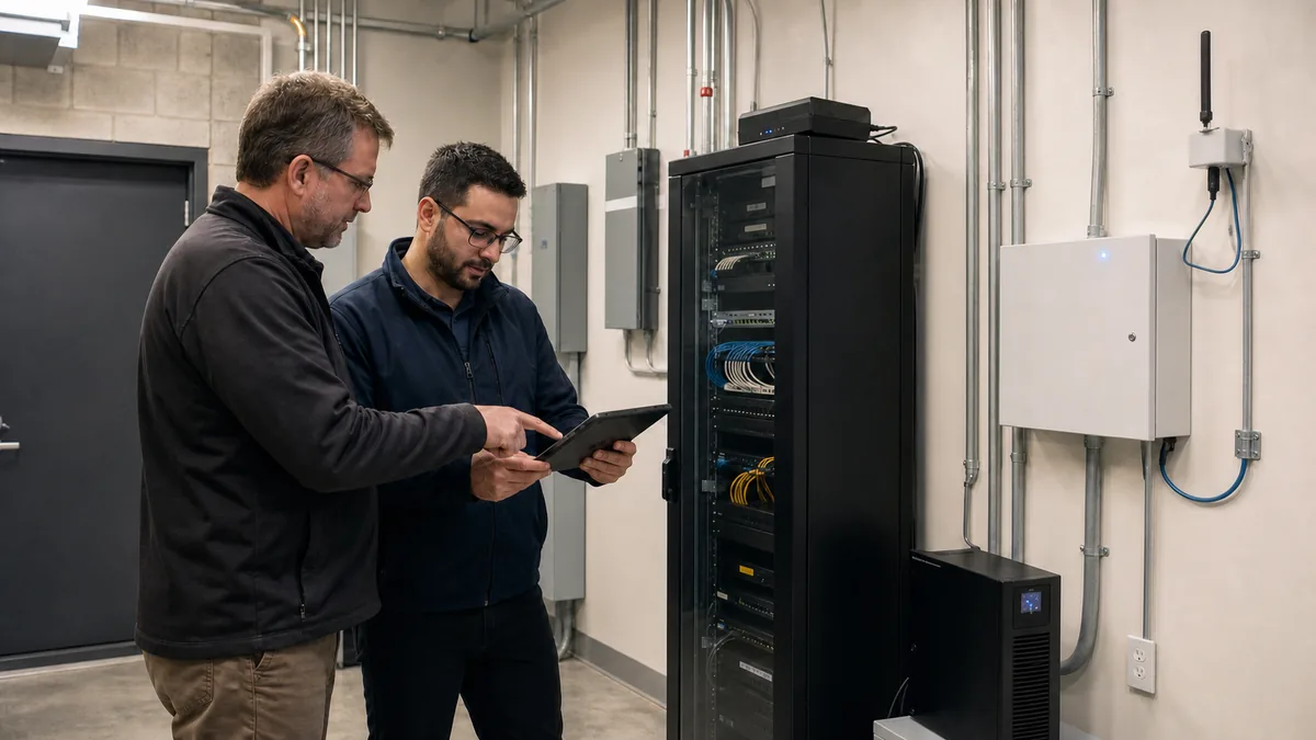
A commercial alarm can detect an intrusion correctly and still fail at the moment the signal must leave the site. Internet equipment can lose power, a cellular radio can have weak indoor coverage, a cable can be cut, a receiver configuration can be wrong, or a trouble event can reach an inbox with no assigned response.
Choose communication paths from an end-to-end failure model. Define the alarm events that must arrive, the maximum tolerable detection and reporting times, the primary route, the backup route, every shared dependency, the supervision method and the person responsible for a path failure. Then prove the design by interrupting each route during an observed test. This framework helps IT, facilities and operations teams evaluate communications for a professionally monitored commercial alarm system.
1. Define the complete signal journey
An alarm communication path begins at the control unit and ends when the correct event is available to the intended receiver and operating workflow. A diagram should show every component between those points:
- alarm control unit and event queue;
- communicator or integrated network interface;
- local Ethernet, Wi-Fi, cellular or legacy connection;
- router, firewall, switch, access point or carrier radio network;
- local and upstream power supplies;
- service provider or communication platform;
- signal receiving centre receiver and automation system; and
- operator procedure, notification and escalation.
Define the required event set before choosing hardware. Alarm, panic, opening and closing, trouble, supervisory, test, restore and maintenance events can have different priorities and handling rules. Confirm that the account number, partition, zone, user and event type remain accurate throughout the journey.
Map who owns each component. Facilities may own the panel and electrical room. IT may own the switch, firewall and internet service. The alarm provider may own the communicator account and receiver programming. The monitoring organization owns the receiving workflow. An unassigned dependency can remain down because every party assumes another party is responding.
2. Choose primary and backup paths from failure domains
IP, cellular and legacy telephone communications expose the site to different failure domains. Select the combination that best addresses the site’s actual risks, applicable requirements and receiver capabilities.
| Path type | Useful characteristics | Dependencies to examine | Test conditions |
|---|---|---|---|
| Wired IP | Can use managed business networking, encryption and existing observability | Communicator port, switch, router, firewall, DNS where used, ISP, cabling and backup power | Disconnect approved Ethernet segment, restart network equipment, simulate ISP loss |
| Wi-Fi or wireless LAN | Can avoid a new data cable where supported | Access point, radio conditions, credentials, controller, VLAN, interference and power | Disable the approved SSID or access point, change signal conditions, verify recovery |
| Cellular | Can avoid the site’s wired internet and exterior data cable | Indoor signal, antenna, carrier coverage, radio technology, subscription, platform and local power | Attenuate or disconnect under controlled conditions, confirm trouble and restoration |
| Legacy telephone or dial capture | May support existing equipment during a managed transition | Line technology, conversion equipment, dial tone emulation, premises power and carrier lifecycle | Remove the line, interrupt conversion equipment and verify reporting behaviour |
A primary path is the route the system normally uses first. A backup path is expected to carry events when the primary route becomes unavailable. Some systems can duplicate events over more than one route. These behaviours have different implications for detection, receiver processing and data use.
The current DMP XR150/XR550 Canadian programming guide provides a concrete product example: it supports multiple communication paths, designates paths as primary or backup, and allows backup use after primary failure or duplicate reporting where configured. This is manufacturer-specific documentation. Confirm the exact panel, communicator, firmware, receiver, service and listing requirements proposed for the site.
3. Test whether two paths are genuinely independent
An IP path and a cellular path use different external networks, yet they may share several local and upstream components. A dual-path label alone cannot establish the level of resilience.
Build a shared-dependency register:
| Dependency | Questions to answer |
|---|---|
| Alarm control unit | Can the panel queue and transmit all required events during a path transition? |
| Communicator | Do both paths use one module, processor, firmware image or interface cable? |
| Power | Do the panel, communicator, modem, router and switch remain powered for the required period? |
| Physical route | Are Ethernet, antenna and power cables exposed to one cut, water event or construction impact? |
| Network edge | Does the IP path depend on one switch, firewall, DNS service or configuration owner? |
| Radio environment | Is the cellular signal reliable inside the final enclosure and through seasonal or building changes? |
| Service platform | Do both paths converge on one vendor cloud, account or gateway before reaching the receiver? |
| Receiving centre | Do the routes terminate on separate receiver resources or one common endpoint? |
| Operations | Will one team recognize, own and escalate either type of failure? |
Classify each dependency as shared, separate or unknown. Unknowns require evidence from the integrator, platform provider, carrier or monitoring organization. A shared component may be acceptable when its reliability, supervision, replacement plan and business impact are understood.
Pay particular attention to backup power. Cellular communications can remain externally available during a local outage while the radio or alarm panel loses local power. An IP communicator may have panel battery support while the site’s switch, modem or firewall shuts down immediately. Record each load, supply, runtime assumption and test result.
4. Specify supervision as a response requirement
Supervision helps determine whether a panel or communication route is still able to check in with its receiver. A useful requirement states:
- which component sends the check-in;
- which receiver expects it;
- how often the check-in occurs;
- how many can be missed;
- when a missing condition is declared;
- where the trouble appears;
- who must acknowledge it;
- the escalation time and restoration target; and
- how a restore event is recorded.
The DMP Canadian guide describes check-in reports as a method of supervising panel communication with a receiver. Its configurable fail time allows multiple check-ins to be missed before the receiver records a panel-not-responding condition. The guide also provides options for how communication trouble is displayed and reported. Those values are programming options for a particular product family. The approved interval for a site must come from its risk, applicable standards, insurance or authority requirements, product listing and monitoring service.
Do not confuse three different conditions:
- Local path trouble: the panel or communicator detects a local interface or radio problem.
- Receiver supervision failure: the receiver does not receive an expected check-in within the configured window.
- End-to-end event failure: a real or test event does not reach the intended monitoring workflow correctly.
A system can pass one condition and fail another. For example, an Ethernet link may remain physically up while upstream routing blocks receiver traffic. An end-to-end test should include receiver evidence and operator handling.
Connect alarm communication troubles to the broader security-system health monitoring process. Set severity from the effect of the failure, remaining path capacity, site status and expected repair time.
5. Coordinate the network path with IT
Treat an IP alarm path as a managed production service. Document the network handoff and the changes that can affect it:
- wired port, switch and VLAN;
- address assignment and reservation where required;
- outbound destinations, ports and protocols supplied by the vendor;
- firewall, proxy, DNS and inspection dependencies;
- bandwidth and data-volume expectations;
- encryption and certificate requirements;
- monitoring and logging available to IT;
- UPS coverage for the complete network chain;
- maintenance windows and change notification; and
- ownership during an incident.
Avoid broad inbound exposure or ad hoc port forwarding unless the supported architecture explicitly requires it and the security implications are approved. Give the alarm device only the network access it needs. Use the vendor’s current documentation and test after firewall, ISP, router, DNS, certificate or switching changes.
The alarm communicator should be included in the site’s networking and data-wiring records. Label the field cable and switch port in the controlled documentation, preserve service loops and physical protection, and keep administrator credentials with the appropriate owner.
6. Engineer the cellular path at the installed location
Cellular performance must be tested where the antenna and communicator will remain. A temporary test beside an open electrical-room door can overstate the installed result. Concrete, metal enclosures, low-e glazing, underground rooms, equipment additions and antenna relocation can change radio performance.
Record:
- communicator model, supported radio technology and service provider;
- antenna type, cable, connector, location and physical protection;
- measured signal indicators available from the supported tool;
- results during ordinary building operation;
- backup power and expected data use;
- subscription owner, renewal method and account status alerts;
- carrier or technology migration responsibility; and
- retest triggers after construction or equipment movement.
If two cellular services are proposed, confirm how the communicator selects or uses them and whether they provide meaningful carrier or infrastructure diversity at that location. A second SIM does not automatically prove separate towers, backhaul, service platform or local power.
Keep antenna and data cables away from likely damage and unauthorized access. Respect manufacturer separation, grounding, enclosure and cable-length requirements. A stronger-looking antenna installation can still fail if connectors, cable loss, mounting or the final enclosure are wrong.
7. Confirm the monitoring and certification boundary
The communication design must match the service that receives and acts on it. UL Solutions Canada’s Fire and Security Alarm Certificate Programs page states that intrusion alarm installation, monitoring and service are addressed by CAN/ULC-S301, CAN/ULC-S302 and CAN/ULC-S304. It also explains that only systems with an active certificate issued and maintained by a ULC Listed company are considered ULC systems under the certificate program.
Ask the monitoring provider to identify:
- the receiving centre and relevant listing or certification scope;
- the receiver and protocol used by each path;
- whether paths are treated as primary, backup or duplicate;
- supervision settings and the resulting missing-panel threshold;
- how path trouble, restore and delayed events are displayed;
- operator instructions for alarm, panic, trouble and test events;
- receiver or data-centre redundancy relevant to the service;
- planned maintenance and failover procedures;
- account ownership and change authorization; and
- reports available for commissioning and recurring review.
Request the certificate when a code authority, insurer, contract or risk decision requires one. A vendor’s ULC listing and an active certificate for the individual system are different facts, as the UL Solutions page explains.
8. Keep intrusion and fire signal requirements separate
Commercial properties can have intrusion, hold-up, fire and sprinkler signals, sometimes through related service organizations. Their applicable standards, authorities, priorities, equipment and procedures differ.
UL Solutions identifies CAN/ULC-S561 for fire and sprinkler protective signalling. The official CAN/ULC-S561 standards page lists the active third edition with a July 22, 2024 revision. The public summary does not expose every prescriptive communication requirement. Obtain the applicable standard, certificate requirements, equipment documentation and authority direction before designing or changing a fire signal path.
Do not apply an intrusion communicator setting to a fire installation from analogy. Keep drawings, approvals, test procedures and service responsibilities explicit for each system. Coordinate any shared equipment or network dependency through the qualified fire-alarm and security providers.
9. Design reporting around the response policy
Successful transport delivers an event to the monitoring centre. The event must also contain enough correct information for the required response.
The Toronto Police Service alarm response page states that burglar alarm calls require verification through audio, video, an eyewitness or multiple zone activations. It excludes panic alarms from that verification requirement and notes that response remains subject to call nature, demand, priorities and available resources.
For Toronto sites, confirm that the panel event set, zone naming, monitoring instructions and available verification method support the current policy. An alarm path that carries only a generic event may limit the monitoring operator’s ability to use multiple-zone information correctly. If video or audio verification is part of the plan, test its own power, network, storage, time synchronization, privacy controls and operator workflow.
Other GTA police services and municipalities can have different alarm registration, false-alarm and response rules. Verify the current policy for each site rather than applying Toronto’s procedure across the region.
10. Run an observed path-failure acceptance test
Coordinate testing with the monitoring station, site contacts and affected operations. Put the account on the correct test status and prevent unintended dispatch. Use an approved method to interrupt one dependency at a time.
Baseline event
- Send each material event type through normal operation.
- Confirm the receiver account, event, partition, zone, timestamp and operator instruction.
- Record local panel and communicator indications.
Primary-path interruption
- Interrupt the primary path at the approved test point.
- Confirm the remaining route carries the required event.
- Measure when local trouble and receiver supervision identify the failure.
- Verify notification, acknowledgement and escalation.
- Restore the path and confirm a recognized restore condition.
Backup-path interruption
Repeat the test with the backup route unavailable while the primary route operates. This proves that the backup is supervised or otherwise checked according to the design before it is urgently needed.
Shared-dependency tests
Test representative shared failures such as network-equipment power loss, communicator restart, upstream internet outage and controlled antenna or cellular-service loss. Confirm queued events, path switching, duplicate-event handling and restoration.
Evidence package
Retain the approved configuration, dependency diagram, receiver report, timestamps, screenshots where permitted, service contacts, exceptions and unresolved deficiencies. Repeat affected tests after communicator, panel, router, firewall, ISP, antenna, cellular service, receiver or monitoring-account changes.
11. Ask vendors questions that reveal the architecture
Use questions that require diagrams and observed evidence:
- Which events use each path, and are they sent sequentially or in duplicate?
- How quickly is each path failure detected locally and at the receiver?
- Which components, power supplies, cable routes, platforms and receivers are shared?
- What happens to queued events during failure and restoration?
- Which exact communicator, firmware, receiver, protocol and service combination is supported?
- How is IP traffic restricted, encrypted and monitored?
- What cellular measurements were taken at the installed antenna location?
- Who owns the cellular subscription and technology migration?
- What UPS loads and tested runtimes cover the full reporting chain?
- Which ULC listing and site certificate requirements apply?
- How do monitoring instructions support the local police response policy?
- What recurring test proves the backup path still works?
- Who receives a communication trouble, and what is the restoration target?
- Which reports will demonstrate delivery, supervision and recovery?
Require answers in the proposal, drawings, cause-and-effect documentation and acceptance plan. A resilient alarm path is an operating service with technical and human dependencies that remain visible after commissioning.
Commercial alarm communications should be selected through failure analysis and proven through controlled interruption. Securitron Canada can help GTA organizations map IP and cellular dependencies, coordinate monitoring requirements and commission reporting paths with IT, facilities and operations teams.
Frequently Asked Questions
Choose from the site's failure risks and response requirements. IP can use managed business networking and may provide strong visibility. Cellular can avoid the site's wired internet path. Many commercial sites use both after confirming that the two routes have suitable coverage, power, receiver support and supervision.
No. Two transmission methods can still share the alarm panel, communicator, power supply, antenna location, cable route, cloud platform or receiving infrastructure. Document each shared dependency and test failures at the points the design claims to tolerate.
Supervision uses check-ins or test messages to help detect that a panel or path has stopped communicating. The effective detection time depends on the configured check-in and fail settings, receiver logic and escalation workflow. Supervision should produce a clear, assigned response rather than an unactioned trouble event.
Coordinate a test window with the monitoring station, send a known event, confirm the correct account and event details, interrupt one path, verify the remaining path delivers, confirm the failure is detected within the approved interval, restore service and repeat for the other path. Record receiver timestamps, local indications, notifications and restoration.